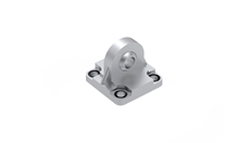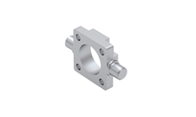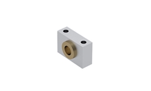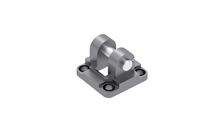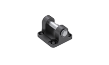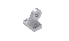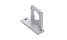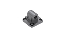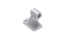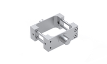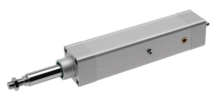
SSG
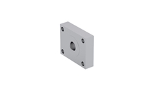
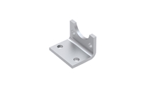
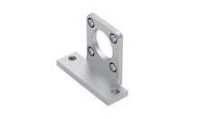
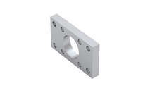
Mounting attachment accessory SSG, aluminium or stainless steel AISI 316
| Designation | Select all | CAD | Compare | Get quote | Lead Time * | Ball Screw (d x l) | Dynamic Load Capacity C (N) | Max. Axial Load Fmax (N) | Max. Drive Torque Mₚ (Nm) | Max. Travel Speed Vmax (m/s) | Max. Rotational Speed nmax (min⁻¹) | No Load Torque M₀ (Nm) | Min. Stroke Smin (mm) | Max. Stroke Smax (mm) | Moved Mass (kg) | Mass of the Electric Cylinder mPNCE (kg) | Mass Moment of Inertia JPNCE (10⁻⁶ kg m²) | |
|---|---|---|---|---|---|---|---|---|---|---|---|---|---|---|---|---|---|---|
|
|
|
2 | 12 × 5 mm | 5000 | 2540 | 2.2 | 0.48 | 5800 | 0.1 | 30 | 800 | 0.32 + 0.0010 × (Absolute stroke + E) | 1.10 + 0.0043 × Absolute stroke + 0.0010 × E | 2.15 + 0.0128 × Absolute stroke + 0.0006 × E + 0.6333 × mload | ||||
|
|
|
2 | 12 × 10 mm | 3800 | 1270 | 2.2 | 0.97 | 5800 | 0.15 | 30 | 800 | 0.32 + 0.0010 × (Absolute stroke + E) | 1.10 + 0.0043 × Absolute stroke + 0.0010 × E | 2.75 + 0.0147 × Absolute stroke + 0.0025 × E + 2.5330 × mload | ||||
|
|
|
2 | 16 × 5 mm | 13150 | 6020 | 5.3 | 0.35 | 4200 | 0.15 | 40 | 900 | 0.44 + 0.0007 × (Absolute stroke + E) | 1.45 + 0.0051 × Absolute stroke + 0.0007 × E | 4.50 + 0.0395 × Absolute stroke + 0.0004 × E + 0.6333 × mload | ||||
|
|
|
2 | 16 × 10 mm | 11550 | 3010 | 5.3 | 0.7 | 4200 | 0.2 | 35 | 900 | 0.44 + 0.0007 × (Absolute stroke + E) | 1.45 + 0.0051 × Absolute stroke + 0.0007 × E | 5.35 + 0.0408 × Absolute stroke + 0.0018 × E + 2.5330 × mload | ||||
|
|
|
2 | 16 × 16 mm | 8170 | 1880 | 5.3 | 1.12 | 4200 | 0.25 | 35 | 900 | 0.44 + 0.0007 × (Absolute stroke + E) | 1.45 + 0.0051 × Absolute stroke + 0.0007 × E | 7.10 + 0.0436 × Absolute stroke + 0.0046 × E + 6.4846 × mload | ||||
|
|
|
2 | 20 × 5 mm | 14800 | 14600 | 12.9 | 0.28 | 3300 | 0.3 | 50 | 1000 | 0.95 + 0.0012 × (Absolute stroke + E) | 2.50 + 0.0073 × Absolute stroke + 0.0012 × E | 17.75 + 0.0817 × Absolute stroke + 0.0007 × E + 0.6333 × mload | ||||
|
|
|
2 | 20 × 10 mm | 15900 | 7830 | 13.9 | 0.55 | 3300 | 0.35 | 55 | 1000 | 0.95 + 0.0012 × (Absolute stroke + E) | 2.50 + 0.0073 × Absolute stroke + 0.0012 × E | 19.55 + 0.0839 × Absolute stroke + 0.0030 × E + 2.5330 × mload | ||||
|
|
|
2 | 20 × 20 mm | 16250 | 3900 | 13.9 | 1.1 | 3300 | 0.4 | 50 | 1000 | 0.95 + 0.0012 × (Absolute stroke + E) | 2.50 + 0.0073 × Absolute stroke + 0.0012 × E | 26.75 + 0.0928 × Absolute stroke + 0.0118 × E + 10.1321 × mload | ||||
|
|
|
2 | 20 × 50 mm | 13000 | 1560 | 13.9 | 2.5 | 3000 | 0.5 | 30 | 1000 | 0.88 + 0.0012 × (Absolute stroke + E) | 2.43 + 0.0073 × Absolute stroke + 0.0012 × E | 73.80 + 0.1549 × Absolute stroke + 0.0740 × E + 63.3257 × mload | ||||
|
|
|
2 | 25 × 5 mm | 16700 | 16500 | 14.6 | 0.23 | 2700 | 0.5 | 40 | 1200 | 1.00 + 0.0011 × (Absolute stroke + E) | 3.05 + 0.0097 × Absolute stroke + 0.0011 × E | 32.55 + 0.2358 × Absolute stroke + 0.0007 × E + 0.6333 × mload | ||||
|
|
|
2 | 25 × 10 mm | 15800 | 15800 | 28 | 0.45 | 2700 | 0.55 | 40 | 1200 | 1.00 + 0.0011 × (Absolute stroke + E) | 3.05 + 0.0097 × Absolute stroke + 0.0011 × E | 34.45 + 0.2378 × Absolute stroke + 0.0028 × E + 2.5330 × mload | ||||
|
|
|
2 | 25 × 25 mm | 16700 | 7940 | 35.1 | 1.13 | 2700 | 0.65 | 30 | 1200 | 0.98 + 0.0011 × (Absolute stroke + E) | 3.03 + 0.0097 × Absolute stroke + 0.0011 × E | 47.30 + 0.2523 × Absolute stroke + 0.0172 × E + 15.8314 × mload | ||||
|
|
|
2 | 32 × 5 mm | 18850 | 18850 | 16.7 | 0.18 | 2150 | 0.65 | 60 | 1500 | 2.15 + 0.0028 × (Absolute stroke + E) | 6.48 + 0.0156 × Absolute stroke + 0.0028 × E | 118.14 + 0.6514 × Absolute stroke + 0.0018 × E + 0.6333 × mload | ||||
|
|
|
2 | 32 × 10 mm | 37000 | 25000 | 44.2 | 0.5 | 3000 | 0.7 | 60 | 1500 | 2.15 + 0.0028 × (Absolute stroke + E) | 6.48 + 0.0156 × Absolute stroke + 0.0028 × E | 122.23 + 0.6567 × Absolute stroke + 0.0071 × E + 2.5330 × mload | ||||
|
|
|
2 | 32 × 20 mm | 22950 | 17160 | 60.7 | 1 | 3000 | 0.75 | 70 | 1500 | 2.15 + 0.0028 × (Absolute stroke + E) | 6.48 + 0.0156 × Absolute stroke + 0.0028 × E | 138.60 + 0.6781 × Absolute stroke + 0.0285 × E + 10.1321 × mload | ||||
|
|
|
2 | 32 × 32 mm | 15500 | 10725 | 60.7 | 1.6 | 3000 | 0.9 | 70 | 1500 | 2.15 + 0.0028 × (Absolute stroke + E) | 6.48 + 0.0156 × Absolute stroke + 0.0028 × E | 172.65 + 0.7227 × Absolute stroke + 0.0731 × E + 25.9382 × mload | ||||
|
|
|
2 | 40 × 5 mm | 23800 | 23800 | 21 | 0.18 | 2200 | 1 | 45 | 1500 | 3.21 + 0.0047 × (Absolute stroke + E) | 10.12 + 0.0245 × Absolute stroke + 0.0047 × E | 342.17 + 1.6613 × Absolute stroke + 0.0030 × E + 0.6333 × mload | ||||
|
|
|
2 | 40 × 10 mm | 38000 | 29000 | 51.3 | 0.37 | 2200 | 1.1 | 55 | 1500 | 3.21 + 0.0047 × (Absolute stroke + E) | 10.12 + 0.0245 × Absolute stroke + 0.0047 × E | 348.27 + 1.6701 × Absolute stroke + 0.0118 × E + 2.5330 × mload | ||||
|
|
|
2 | 40 × 20 mm | 33300 | 29000 | 102.6 | 0.73 | 2200 | 1.2 | 65 | 1500 | 3.21 + 0.0047 × (Absolute stroke + E) | 10.12 + 0.0245 × Absolute stroke + 0.0047 × E | 372.67 + 1.7056 × Absolute stroke + 0.0473 × E + 10.1321 × mload | ||||
|
|
|
2 | 40 × 40 mm | 35000 | 22980 | 162.6 | 1.47 | 2200 | 1.4 | 80 | 1500 | 3.54 + 0.0047 × (Absolute stroke + E) | 10.61 + 0.0245 × Absolute stroke + 0.0047 × E | 483.41 + 1.8476 × Absolute stroke + 0.1893 × E + 40.5285 × mload |
*Green: Normally in stock, contact us for current status. Blue: Contact us for delivery time.
| Designation | Select all | CAD | Compare | Get quote | L1 | L2 | L3 | L4 | L5 | L6 | L7 | L8 | P1 | P2 | P3 | P4 | P5 | P6 | P7 | G | D1 | D2 | D3 | D4 | M1 | M2 | M3 | H | A1 | A2 | A3 | ZK1 | ZK2 | ZK3 | V1 | V2 | |
|---|---|---|---|---|---|---|---|---|---|---|---|---|---|---|---|---|---|---|---|---|---|---|---|---|---|---|---|---|---|---|---|---|---|---|---|---|---|
|
|
|
136 (+0.2/-1.4) | 48 | 21 | 26 (+1.9/-0.8) | 15 | 22.5 | 20 | 15 | 30 | 30 | 5 | 4 (±0.1) | 18 (±0.1) | 47 | 32.5 | G 1/8 | Ø 18 (f8) | Ø 30 (d11) | Ø 6 (h7) | Ø 30 (g7) | Ø M10 × 1.25 | Ø M10 × 1.25 | M6 | Ø 8 | 22 | 5 | 5 | 10 | 17 | 16 | 16 | 4.5 | ||||
|
|
|
136 (+0.2/-1.4) | 48 | 21 | 26 (+1.9/-0.8) | 15 | 22.5 | 20 | 15 | 30 | 30 | 5 | 4 (±0.1) | 18 (±0.1) | 47 | 32.5 | G 1/8 | Ø 18 (f8) | Ø 30 (d11) | Ø 6 (h7) | Ø 30 (g7) | Ø M10 × 1.25 | Ø M10 × 1.25 | M6 | Ø 8 | 22 | 5 | 5 | 10 | 17 | 16 | 16 | 4.5 | ||||
|
|
|
144 (+0.2/-1.4) | 54 | 25 | 30 (+1.9/-0.8) | 15 | 22.5 | 20 | 18 | 30 | 30 | 5 | 4 (±0.1) | 20 (±0.1) | 54 | 38 | G 1/8 | Ø 20 (f8) | Ø 35 (d11) | Ø 8 (h7) | Ø 35 (g7) | Ø M12 × 1.25 | Ø M12 × 1.25 | M6 | Ø 8 | 24 | 6 | 6 | 13 | 19 | 17 | 16 | 4.5 | ||||
|
|
|
144 (+0.2/-1.4) | 54 | 25 | 30 (+1.9/-0.8) | 15 | 22.5 | 20 | 18 | 30 | 30 | 5 | 4 (±0.1) | 20 (±0.1) | 54 | 38 | G 1/8 | Ø 20 (f8) | Ø 35 (d11) | Ø 8 (h7) | Ø 35 (g7) | Ø M12 × 1.25 | Ø M12 × 1.25 | M6 | Ø 8 | 24 | 6 | 6 | 13 | 19 | 17 | 16 | 4.5 | ||||
|
|
|
144 (+0.2/-1.4) | 54 | 25 | 30 (+1.9/-0.8) | 15 | 22.5 | 20 | 18 | 30 | 30 | 5 | 4 (±0.1) | 20 (±0.1) | 54 | 38 | G 1/8 | Ø 20 (f8) | Ø 35 (d11) | Ø 8 (h7) | Ø 35 (g7) | Ø M12 × 1.25 | Ø M12 × 1.25 | M6 | Ø 8 | 24 | 6 | 6 | 13 | 19 | 17 | 16 | 4.5 | ||||
|
|
|
180 (+0.2/-1.4) | 69 | 32 | 37 (+1.9/-0.8) | 15 | 22.5 | 20 | 25 | 36 | 37 | 5 | 4 (±0.1) | 25 (±0.1) | 65 | 46.5 | G 1/8 | Ø 25 (f8) | Ø 40 (d11) | Ø 11 (h7) | Ø 40 (g7) | Ø M16 × 1.5 | Ø M16 × 1.5 | M8 | Ø 8 | 32 | 8 | 8 | 17 | 24 | 22 | 18 | 4.5 | ||||
|
|
|
180 (+0.2/-1.4) | 69 | 32 | 37 (+1.9/-0.8) | 15 | 22.5 | 20 | 25 | 36 | 37 | 5 | 4 (±0.1) | 25 (±0.1) | 65 | 46.5 | G 1/8 | Ø 25 (f8) | Ø 40 (d11) | Ø 11 (h7) | Ø 40 (g7) | Ø M16 × 1.5 | Ø M16 × 1.5 | M8 | Ø 8 | 32 | 8 | 8 | 17 | 24 | 22 | 18 | 4.5 | ||||
|
|
|
180 (+0.2/-1.4) | 69 | 32 | 37 (+1.9/-0.8) | 15 | 22.5 | 20 | 25 | 36 | 37 | 5 | 4 (±0.1) | 25 (±0.1) | 65 | 46.5 | G 1/8 | Ø 25 (f8) | Ø 40 (d11) | Ø 11 (h7) | Ø 40 (g7) | Ø M16 × 1.5 | Ø M16 × 1.5 | M8 | Ø 8 | 32 | 8 | 8 | 17 | 24 | 22 | 18 | 4.5 | ||||
|
|
|
180 (+0.2/-1.4) | 69 | 32 | 37 (+1.9/-0.8) | 15 | 22.5 | 20 | 25 | 36 | 37 | 5 | 4 (±0.1) | 25 (±0.1) | 65 | 46.5 | G 1/8 | Ø 25 (f8) | Ø 40 (d11) | Ø 11 (h7) | Ø 40 (g7) | Ø M16 × 1.5 | Ø M16 × 1.5 | M8 | Ø 8 | 32 | 8 | 8 | 17 | 24 | 22 | 18 | 4.5 | ||||
|
|
|
171 (+0.2/-1.4) | 69 | 38 | 37 (+1.9/-0.8) | 15 | 22.5 | 20 | 25 | 38 | 38 | 5 | 4 (±0.1) | 25 (±0.1) | 75 | 56.5 | G 1/8 | Ø 30 (f8) | Ø 45 (d11) | Ø 15 (h7) | Ø 45 (g7) | Ø M16 × 1.5 | Ø M16 × 1.5 | M8 | Ø 8 | 32 | 8 | 8 | 17 | 24 | 27 | 18 | 4.5 | ||||
|
|
|
171 (+0.2/-1.4) | 69 | 38 | 37 (+1.9/-0.8) | 15 | 22.5 | 20 | 25 | 38 | 38 | 5 | 4 (±0.1) | 25 (±0.1) | 75 | 56.5 | G 1/8 | Ø 30 (f8) | Ø 45 (d11) | Ø 15 (h7) | Ø 45 (g7) | Ø M16 × 1.5 | Ø M16 × 1.5 | M8 | Ø 8 | 32 | 8 | 8 | 17 | 24 | 27 | 18 | 4.5 | ||||
|
|
|
171 (+0.2/-1.4) | 69 | 38 | 37 (+1.9/-0.8) | 15 | 22.5 | 20 | 25 | 38 | 38 | 5 | 4 (±0.1) | 25 (±0.1) | 75 | 56.5 | G 1/8 | Ø 30 (f8) | Ø 45 (d11) | Ø 15 (h7) | Ø 45 (g7) | Ø M16 × 1.5 | Ø M16 × 1.5 | M8 | Ø 8 | 32 | 8 | 8 | 17 | 24 | 27 | 18 | 4.5 | ||||
|
|
|
204 (+0.2/-1.4) | 86 | 40 | 46 (+1.9/-0.8) | 15 | 22.5 | 20 | 30 | 40 | 40 | 18 | 14 (±0.1) | 31 (±0.1) | 93 | 72 | G 1/8 | Ø 40 (f8) | Ø 60 (d11) | Ø 18 (h7) | Ø 60 (g7) | Ø M20 × 1.5 | Ø M12 | M10 | Ø 8 | 40 | 8 | 10 | 22 | 30 | 32 | 17 | / | ||||
|
|
|
204 (+0.2/-1.4) | 86 | 40 | 46 (+1.9/-0.8) | 15 | 22.5 | 20 | 30 | 40 | 40 | 18 | 14 (±0.1) | 31 (±0.1) | 93 | 72 | G 1/8 | Ø 40 (f8) | Ø 60 (d11) | Ø 18 (h7) | Ø 60 (g7) | Ø M20 × 1.5 | Ø M12 | M10 | Ø 8 | 40 | 8 | 10 | 22 | 30 | 32 | 17 | / | ||||
|
|
|
204 (+0.2/-1.4) | 86 | 40 | 46 (+1.9/-0.8) | 15 | 22.5 | 20 | 30 | 40 | 40 | 18 | 14 (±0.1) | 31 (±0.1) | 93 | 72 | G 1/8 | Ø 40 (f8) | Ø 60 (d11) | Ø 18 (h7) | Ø 60 (g7) | Ø M20 × 1.5 | Ø M12 | M10 | Ø 8 | 40 | 8 | 10 | 22 | 30 | 32 | 17 | / | ||||
|
|
|
204 (+0.2/-1.4) | 86 | 40 | 46 (+1.9/-0.8) | 15 | 22.5 | 20 | 30 | 40 | 40 | 18 | 14 (±0.1) | 31 (±0.1) | 93 | 72 | G 1/8 | Ø 40 (f8) | Ø 60 (d11) | Ø 18 (h7) | Ø 60 (g7) | Ø M20 × 1.5 | Ø M12 | M10 | Ø 8 | 40 | 8 | 10 | 22 | 30 | 32 | 17 | / | ||||
|
|
|
224 (+0.2/-1.4) | 91 | 50 | 46 (+1.9/-0.8) | 15 | 22.5 | 20 | 30 | 42 | 42 | 20 | 18 (±0.1) | 34 (±0.1) | 110 | 89 | G 3/8 | Ø 50 (f8) | Ø 70 (d11) | Ø 25 (h7) | Ø 60 (g7) | Ø M20 × 1.5 | Ø M12 | M10 | Ø 12 | 40 | 8 | 10 | 22 | 30 | 40 | 17 | / | ||||
|
|
|
224 (+0.2/-1.4) | 91 | 50 | 51 (+1.9/-0.8) | 25 | 28.5 | 28 | 30 | 42 | 42 | 20 | 18 (±0.1) | 34 (±0.1) | 110 | 89 | G 3/8 | Ø 50 (f8) | Ø 70 (d11) | Ø 25 (h7) | Ø 70 (g7) | Ø M20 × 1.5 | Ø M12 | M10 | Ø 12 | 40 | 6 | 10 | 22 | 30 | 40 | 17 | / | ||||
|
|
|
224 (+0.2/-1.4) | 91 | 50 | 51 (+1.9/-0.8) | 25 | 28.5 | 28 | 30 | 42 | 42 | 20 | 18 (±0.1) | 34 (±0.1) | 110 | 89 | G 3/8 | Ø 50 (f8) | Ø 70 (d11) | Ø 25 (h7) | Ø 70 (g7) | Ø M20 × 1.5 | Ø M12 | M10 | Ø 12 | 40 | 6 | 10 | 22 | 30 | 40 | 17 | / | ||||
|
|
|
239 (+0.2/-1.4) | 91 | 50 | 51 (+1.9/-0.8) | 25 | 28.5 | 28 | 30 | 42 | 42 | 20 | 18 (±0.1) | 34 (±0.1) | 110 | 89 | G 3/8 | Ø 50 (f8) | Ø 70 (d11) | Ø 25 (h7) | Ø 70 (g7) | Ø M20 × 1.5 | Ø M12 | M10 | Ø 12 | 40 | 6 | 10 | 22 | 30 | 40 | 17 | / |